Lorentz force acting on non-magnetic thin plate elements
- TOP >
- Analysis Examples by Functions (List) >
- Lorentz force acting on non-magnetic thin plate elements
Summary
EMSolution provides non-magnetic thin plate elements. It is applicable to non-magnetic conductor plates whose thickness is sufficiently small compared to the skin thickness and is defined as a face element. Modeling with three-dimensional solid elements slows down the convergence of the ICCG method because of the very flat elements, but this is not the case with non-magnetic thin plate elements. Another advantage is that meshing becomes easier.
Explanation
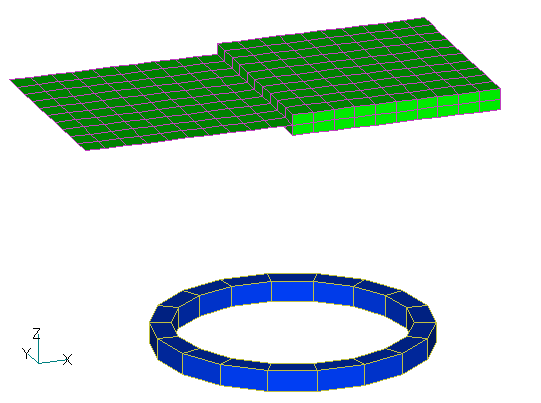
Previously, electromagnetic forces acting on non-magnetic thin plate elements were only calculated using the nodal force method, but we are pleased to report that we have added a function to calculate the Lorentz force (
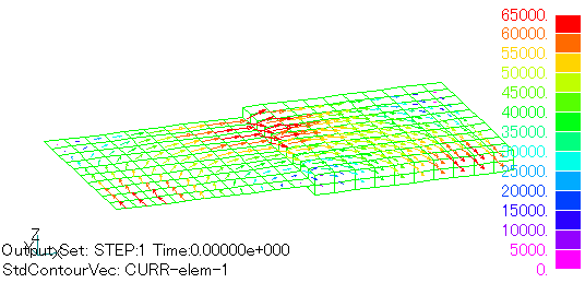
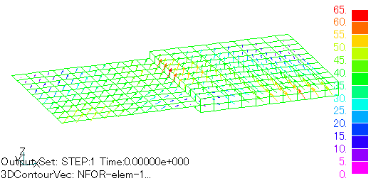
Fig. 2 shows the eddy current distribution at phase zero obtained by the analysis. Fig. 3 shows the electromagnetic force density distribution obtained by the nodal force method, and Fig. 4 shows the electromagnetic force density distribution due to Lorentz force, which is a newly added function. The nodal force method and the Lorentz force method are in good agreement on the plane element side.
Next, the analytical results of the integrated force in each region are shown.
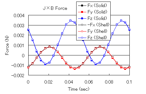
Figs. 5 and 6 show the time variation of the integrated force in each direction on the solid element side and the face element side using the nodal force method and Lorentz force method, respectively. The agreement between the two is good, and the symmetry between the solid side and the face element side is also good. In other words, we can see the relationship Fx(Solid)=-Fx(Shell), Fy(Solid)=Fy(Shell), and Fz(Solid)=Fz(Shell). Fx on the face element side is shown with positive and negative values reversed for easy comparison.
The electromagnetic force acting on the coil is calculated by the new function "COIL (external current magnetic field source)". The force acting on the conductor and the force acting on the coil are in an action-reaction relationship and should be equal in the opposite direction, which is also the case in the calculation results.
As described above, the analytical results of the electromagnetic force by Lorentz force are in good agreement with those by the nodal force method and are reasonable. Although the Lorentz force and the electromagnetic force by the nodal force method should agree with each other in non-magnetic conductors, there are many cases where the agreement is not good due to numerical errors. We believe that the surface element approximation can be used to compare the two, which may be useful in examining the accuracy of the electromagnetic force. In addition, when there is a weak magnetic field fluctuation in a strong magnetic field, the nodal force may not be accurate. Electromagnetic force due to nodal force may be calculated even in static magnetic fields where it should not appear. In such cases, the Lorentz force is considered more appropriate. For more information on the relationship between Lorentz force and nodal force, please click here.
How to use
The output of electromagnetic force due to Lorentz force for non-magnetic thin plate elements can be the same as for conventional solid elements. Flag FORCE_J_B in the output file FORCE_J_B in "Handbook 10. Input/Output Files" to output the electromagnetic force for non-magnetic thin plate elements. For the element quantity, setting FORCE_J_B=1 will output the element integral force (N), and setting FORCE_J_B=2 will output the volumetric electromagnetic force density (
Download
・ input
・ pre_geom.neu
Analysis Examples by Functions
Non-magnetic thin plate face elements
- Nodal and Lorentz forces in nonmagnetic materials
- Analysis of Rectangular Spiral Inductors
- Cutting of thin Conductor surfaces with gap elements (Part 2)
- Cutting of thin conductor surfaces with gap elements (Part 1)
- Analysis of Anisotropic Nonmagnetic Thin Plates
- Analysis of Nonmagnetic Thin Plates with Surface Elements
- Lorentz force acting on non-magnetic thin plate elements
©2020 Science Solutions International Laboratory, Inc.
All Rights reserved.


