Steady-state current field analysis of porous materials
- TOP >
- Analysis Examples by Functions (List) >
- Steady-state current field analysis of porous materials
Summary
This section introduces the steady-state current field analysis function using a simple model. This function is implemented together with the "Electrostatic Field Analysis" function and allows you to obtain the steady-state current distribution in a conductor when DC is applied. If you want to obtain the magnetic field distribution due to the current as well, please refer to "DC Current Field Analysis".
Explanation
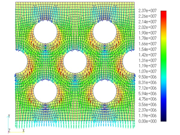
A two-dimensional analysis is performed using the conductor model simulating the porous material shown in Fig. 1. A DC current of 10 A is applied from the top surface, and the granular conductor is set to 1/10 of the conductivity of the surrounding conductors. Periodic boundary conditions are assumed in the left and right directions. Fig. 2 shows the current density distribution diagram. Since the conductivities differ by a factor of 10, it can be seen that the current flows in such a way as to almost avoid the granular conductors.
Next, let us analyze the granular conductor as a nonconductor. Fig. 3 shows the current density distribution, which is almost the same as in Fig. 2, but the current entering the nonconductor is zero.
This is a brief introduction to steady-state current field analysis. Since this function only models the conductive part, no mesh is needed for the non-conductive part such as air. It is useful when you want to analyze a steady-state current field.
Next, let us analyze a granular conductor as a nonconductor. Fig. 3 shows the current density distribution, which is almost the same as in Fig. 2, but the current entering the nonconductor is zero.
This is a brief introduction to steady-state current field analysis. This function models only the conductive part, so meshing of air and other non-conductive parts is not necessary. It is useful when you want to analyze a steady-state current field.
How to use
Please set STATIC=3: Steady Current Field Analysis (see "2. Type of Analysis" of Handbook) and set the following:
(i) Set SIGMA in Hand book "15.1.2 Volume Element Characteristics".
(ii) Set Equipotential Surface Electric Field Sources in Hand book "17.9 Equipotential Surface Electric Field Sources".
- POT_OR_CHARGE=0:Total current passing through the equipotential surface SURFACE_ID [A]
- POT_OR_CHARGE=1:Electric potential applied to equipotential surface SURFACE_ID [V]
Note : Values should be specified by TIME_ID.
Download
Analysis Model
・ input2D.ems
・ pre_geom2D.neu
Analysis Examples by Functions
Electrostatic field
©2020 Science Solutions International Laboratory, Inc.
All Rights reserved.


