Analysis of laminated iron cores by homogenization method and output of magnetic flux density of iron section of laminated iron core
- TOP >
- Analysis Examples by Functions (List) >
- Analysis of laminated iron cores by homogenization method and output of magnetic flux density of iron section of laminated iron core
Summary
When performing a magnetic field analysis of a model that includes a laminated iron core, since the laminated iron core consists of electromagnetic steel plates laminated through an insulating layer, it is very computationally demanding and practically difficult to analyze the fine structure by dividing it directly into elements. The laminated iron core may be treated as an iron core in which eddy currents do not flow and analyzed with conductivity set to zero. The eddy currents caused by the in-plane component of the magnetic field (perpendicular to the lamination) are small, so there should be no problem in treating the conductivity as zero. However, when there is a stacking direction (parallel to the stacking) component of the magnetic field, it is known that the magnetic flux density concentrates on the surface of the stacked iron core, causing a large eddy current loss.
As a modeling method for laminated iron cores, EMSolution has already prepared a homogenization method (PACKING) function and recently released the method. The homogenization method treats the heterogeneous iron core, consisting of steel plates and their insulating layers on the microscopic level, as an equivalent material on the macroscopic level, and was initially applied to nonlinear static magnetic field analysis. Recently, it has also been applied to low-frequency eddy current analysis and shown to agree well with experiments [ref. 1]. Conventionally, the magnetic flux density output from analysis using the homogenization method is the homogenized magnetic flux density, which is somewhat smaller than the magnetic flux density of the laminated steel plate (iron section). Accuracy can be improved by using the magnetic flux density of the iron section instead of the homogenized magnetic flux density, for example, in iron loss calculations.
Explanation
The relationship between the homogenized magnetic field strength $H$ and the magnetic flux density $B$ by the homogenization method can be expressed using the equivalent magnetoresistivity $N$ as follows
$$ \begin{eqnarray} H_\parallel = N_\parallel B_\parallel\\ H_\perp = N_\perp B_\perp\\ \end{eqnarray} (1)$$
where the subscripts $\parallel$ and $\perp$ denote the in-plane and stacking direction, respectively. The equivalent magnetoresistivity can be expressed by the following equation using the magnetoresistivity $\nu_s$ of the iron part and the magnetoresistivity $\nu_0$ of the air gap part.
$$ \begin{eqnarray} \frac{1}{N_\parallel} \equiv \frac{\alpha}{\nu_s (b_s)} + \frac{1 – \alpha}{\nu_0}\\ N_\perp \equiv \alpha \nu_s ( b_s ) + ( 1 – \alpha ) \nu_0\\ \end{eqnarray} (2)$$
where $\alpha$ is the occupancy factor. The magnetic flux density of the iron section, $b_s$, is expressed using the homogenized magnetic flux density, which is
$$ \begin{eqnarray} b_{s \parallel} = \frac{N_\parallel}{\nu_s (b_s)} B_\parallel\\ b{s \perp} = B_\perp\\ \end{eqnarray} (3)$$
and the magnetic flux density of the iron part is approximately 1/$\alpha$ times larger than the homogenized magnetic flux density in the in-plane direction.
The homogenization method approximates the laminated iron core as a homogeneous material with anisotropy.
For an analysis including eddy currents, the equivalent conductivity $\Sigma$ is given by the following equation
$$\Sigma_\perp \equiv \alpha \sigma_s \Sigma_\perp \equiv 0 (4)$$
where $\sigma_s$ is the conductivity of the iron section. This means that only eddy currents in the in-plane direction are considered.
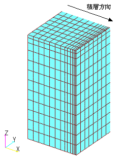
This is applicable when the eddy current distribution in the lamination direction is uniform and the magnetic field can be regarded as constant, i.e., when the skin effect on the steel plate is sufficiently small in the low frequency range. As an example, nonlinear transient analysis including eddy currents is performed using the "IEEJ three-dimensional magnetostatic field verification model" that is used in "Magnetostatic field analysis using COIL (external current magnetic field source)" shown in Fig. 1. Suppose that the laminated iron core is stacked in the x-axis direction with an occupancy ratio of 96%. Since the magnetic flux density is concentrated on the surface of the laminated iron core and at the corners, the mesh in these areas is divided into sections about the thickness of a steel plate, although the mesh is a little coarse.
For comparison, we compare the following four methods of approximating the iron core: (a) with conductivity $\sigma = \sigma_s$, (b) with conductivity $\sigma = 0$, (c) with conductivity $\sigma_\parallel = \sigma_s$ and $\sigma_\perp = 0$, and (d) by combining the homogenization method and the equivalent conductivity $\Sigma$ of equation (4).
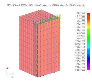
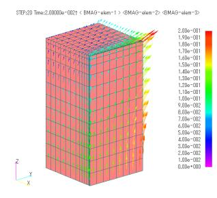
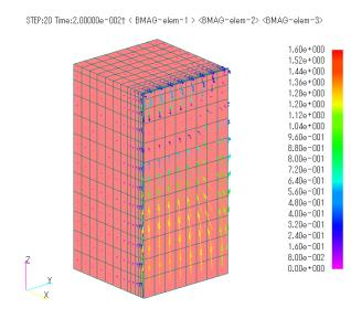
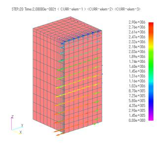
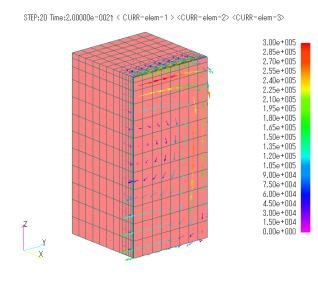
Fig. 2 shows the magnetic flux density vector distribution obtained from the analysis. Fig.3 shows the eddy current distribution obtained by FEM analysis. Since the eddy currents in (b) cannot be obtained by FEM analysis because $\sigma = 0$, results for (a), (c), and (d) are shown. The eddy current distribution in (a) is affected by the roughness of the mesh in the y direction, but as a whole, eddy currents around the surface of the iron core are generated. In (c) and (d), eddy currents looping in the lamination plane (yz plane) are generated due to zero conductivity in the lamination direction. Comparing (c) and (d), eddy currents are more concentrated on the iron core surface in the homogenization method in (d).
Table I shows the results of iron loss output using the " post-processing iron loss calculation " function. Here, the calculation method ① uses the maximum absolute value of the magnetic flux density, and the calculation method ② is calculated directly from the magnetic flux density waveform. The result of the homogenization method in (d) is calculated using the magnetic flux density of the iron part of the laminated iron core according to formula (3). Since (a) is not approximated as a laminated iron core and the iron loss due to post-processing cannot be obtained, only the eddy current loss from the FEM analysis result is used. In (b), $\sigma = 0$ is used, so the eddy current loss in the in-plane direction of the lamination by FEM, which should be there, is not taken into account. Therefore, please note that this result cannot be compared with other results. Compared to (a), losses are greatly reduced in (c) and (d). Comparing (c) and (d), the difference in the maximum value of magnetic flux density appears due to the equivalent magnetoresistivity considered in the homogenization method in (d), which also appears in eddy current loss and hysteresis loss in the stacking direction.
Fig.2 Magnetic flux density distribution (unit: [ $T$ ])
Fig.3 Eddy current density distribution (unit: [ $W/m^3$ ] )
Table I. Iron Losses
| (a) $σ=σ_s$ | (b) $σ=0$ | (c) $σ||=σ_s$ , $σ⊥=0$ | (d) Homogenization method | ||||
| Calculation Method① | Calculation Method② | Calculation Method① | Calculation Method② | Calculation Method① | Calculation Method② | ||
| In-plane method eddy current loss [ $W$ ] | 113.98 | × | × | 1.00 | 1.00 | 0.96 | 0.96 |
| Lamination method eddy current loss [ $W$ ] | - | 0.12 | 0.12 | 0.33 | 0.36 | 0.40 | 0.48 |
| Hysteresis loss [ $W$ ] | - | 0.49 | 0.49 | 1.34 | 1.35 | 1.66 | 1.66 |
| Total [ $W$ ] | 113.98 | 0.60 | 0.61 | 2.67 | 2.71 | 3.02 | 3.10 |
References
[1] Hiroyuki Kaimori, Akihisa Kameari, and Koji Fujiwara, “FEM Computation of Magnetic Field and Iron Loss in Laminated Iron Core Using Homogenization Method” IEEE Transactions on Magnetics 43(4):1405 – 1408, May (2007)
How to use
The magnetic flux density of the iron section of the laminated iron core can be output by post-processing. Since the magnetic flux density of the iron section is considered to be mainly used for iron loss calculations, it is output simultaneously with the iron loss calculation. For details on setting the iron loss parameters, please refer to " Post-processing iron loss calculation ".
The magnetic flux density of the iron section can also be output in the local coordinates assigned to PACKING for convenience when it is used separately in other iron loss calculation methods. In this case, $x$, $y$ ($r$, $\theta$) are the in-plane direction and $z$ is the stacking direction.
First, an example input for (PACKING) is shown, which is set in the EMSolution Handbook “16.1.1 Volume Element Properties”. Although it can be applied to nonlinear static magnetic field analysis, we assume here that this is a nonlinear transient analysis including eddy currents used as an example. Specify the BH data ID in B_H_CURVE_ID, enter a negative value for conductivity since it is anisotropic, and enter an occupancy factor in PACKING. In the next column, enter the anisotropy of conductivity by occupancy ratio, and in the column after that, enter the stacking direction. However, for cylindrical coordinate systems, only the z-direction can be set as the stacking direction. The flux density output to the magnetic file as a transient analysis result including eddy currents is the homogenized flux density.
After the above calculations are completed, the magnetic flux density of the iron section is output as post-processing. This is done at the same time with " Post-processing iron loss calculation ". So AVERAGE must be set to 1 and IRON_LOSS must be set to 1 ($W/kg$) or 2 ($W/m^3$), as described in usage (3) of “Post-processing iron loss calculation”. Then, set 1: Overall coordinate system or 2: Local coordinate system (stacking direction $x$, $y$: in-plane direction, $z$: stacking direction) to specify the output coordinate system of the magnetic flux density of the iron section in the output option MAGNETIC of the magnetic flux density.
Next, you need to enter the parameters required for the iron loss calculation in Usage ⑥ and ⑦. Note that some values must be entered even if iron loss calculation is not required. The COORD_ID set in Iron Loss must be equal to the COORD_ID specified for PACKING.
This function can output magnetic flux density in any local coordinate system specified in the iron loss calculation parameters by setting MAGNETIC=2, even if the PACKING option in Examples (b) and (c) is not used. However, the iron loss calculation will use the z-direction of the specified coordinates as the stacking direction. In the example, it is necessary to define LOCAL_COORDINATE in which the x-direction, which is the stacking direction in the global coordinates, is the z-direction in the local coordinates, and specify it in the COORD_ID of the iron loss calculation parameter.
Download
$\sigma = 0$
・ input_sigma0
・ input_Post_sigma0
・ pre_geom2D.neu :Mesh file
・ 2D_to_3D :3D extension file
$\sigma_\parallel = \sigma_s$ , $\sigma_\perp = 0$
・ input_sigmaX=0
・ input_Post_sigmaX=0
・ pre_geom2D.neu :Mesh file
・ 2D_to_3D :3D extension file
Packing (homogenization method)
・ input_packing
・ input_Post_Biron
・ pre_geom2D.neu :Mesh file
・ 2D_to_3D :3D extension file
Analysis Examples by Functions
Iron loss, permanent magnets and laminated iron cores
- Iron loss calculation using half-cycle periodicity
- Analysis of laminated iron cores by homogenization method and output of magnetic flux density of iron section of laminated iron core
- Analysis using nonlinear two-dimensional anisotropic magnetic properties
- Magnetization input to MAGNET by function
- Iron loss calculation by post-processing
- Evaluation of the rate of decrease from the input magnetization to the operating point and permeance coefficient of permanent magnets
- Demagnetization analysis of permanent magnets
- Analysis considering temperature dependence of magnetization properties
©2020 Science Solutions International Laboratory, Inc.
All Rights reserved.


