Evaluation of the rate of decrease from the input magnetization to the operating point and permeance coefficient of permanent magnets
- TOP >
- Analysis Examples by Functions (List) >
- Evaluation of the rate of decrease from the input magnetization to the operating point and permeance coefficient of permanent magnets
Summary
Generally, embedded permanent magnet type rotating machines (IPM motors) are operated with field weakening control by increasing the current advance angle in order to reduce the induced voltage due to the magnet flux at high speeds, taking advantage of their characteristics. If the magnetic flux generated by the armature winding is too large, the operating point of the permanent magnet may exceed the knee point, resulting in irreversible demagnetization.
In actual motor design, the operating point is often determined to prevent irreversible demagnetization, so we have created a function to calculate the permeance coefficient by post-processing. This allows the possibility of irreversible demagnetization to be shown. It also calculates the rate of decrease from the input (initial) magnetization to the operating point, taking into account the demagnetizing field.
Starting with EMSolution r12.0.3, nonlinear analysis including irreversible demagnetization can be handled. For details, see "Demagnetization Analysis of Permanent Magnets".
Explanation
Here, the rate of decrease from the input magnetization to the operating point and the permeance coefficient are defined as follows:
-
Rate of decrease from input magnetization to operating point
The rate of decrease from the input magnetization (
to the operating point ( -
Permeance coefficient
The permeance coefficient is expressed as
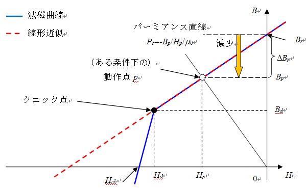
An image of demagnetization by demagnetizing field is shown in Fig. 1. Since EMSolution treats the magnet as a linear material, the operating point moves on the red dotted line. Under certain conditions, the magnetic flux density
Based on the above idea, we have prepared a function to calculate the permeance coefficient and the rate of decrease from the input magnetization to the operating point in the post-processing of EMSolution.
Analysis example
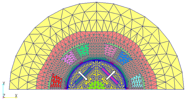
An example of calculating the rate of decrease from the input magnetization to the operating point and permeance coefficient using the D1 model, an IEEJ benchmark motor, is shown in Fig. 2. Note that all analyses are two-dimensional.Table 1 summarizes the calculation conditions for permanent magnets.
Table1 Calculation conditions for permanent magnets
| Type | |
| Magnet orientation | Parallel |
| Magnetization [T] | 1.225 |
| specific magnetic permeability | 1.05 |
| Dimensions [mm] | 220 ( Height 60 ) |
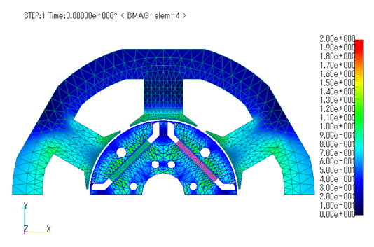
First, the results of the no-load operation analysis are shown. Fig. 3 shows the magnetic flux density distribution at the first step, and Figs. 4 and 5 show the maximum rate of decrease from the input magnetization to the operating point and the minimum permeance coefficient at one cycle of the electric angle. A decrease rate of 1 from the input magnetization to the operating point means 100% reduction. Due to the formation of the magnetic circuit, the reduction is small, with a maximum reduction of about 21%.
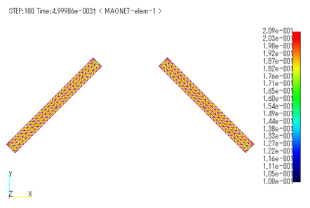
Fig.4 Maximum rate of decrease distribution from input magnetization
to operating point for one cycle of electric angle (No-load operation)
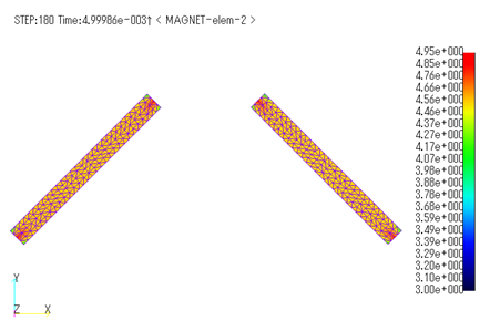
Fig.5 Distribution of the minimum permeance coefficient
for one cycle of electric angle [H] (No-load operation)
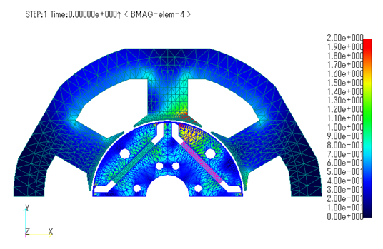
Next, the results are shown for a field weakening condition with a speed of 6000

Fig.7 Maximum rate of decrease distribution from input magnetization
to operating point for one cycle of electric angle (Field weakening operation)
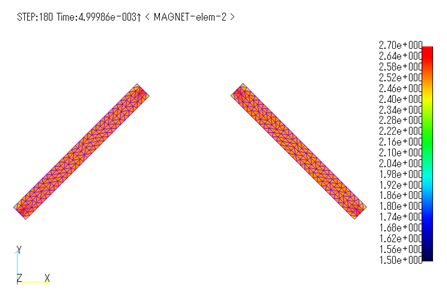
Fig.8 Distribution of the minimum permeance coefficient
for one cycle of electric angle [H] (Field weakening operation)
From the above, we can show the possibility of demagnetization without executing irreversible demagnetization analysis.
How to use
This calculation is done by post-processing (set POST_PROCESSING = 1).
When MAGNETIZATION = 2, the distribution of the rate of decrease from the input magnetization to the operating point is output to MAGNET-elem-1 in the magnetization file, and the permeance coefficient ( H ) is output to MAGNET-elem-2, respectively, as elemental quantities. It also outputs the distribution of the maximum rate of decrease and minimum permeance coefficient for one cycle when AVERAGE = 1.
Download
D1 model (concentrated winding IPM motor)
- Mesh data:
- pre_geom2D.neu (Stator mesh)
- rotor_mesh2D.neu (Rotor mesh)
- No load operation:
- input2D_static_6000rpm_p2.ems
(Static field analysis for initial values) - input2D_transient_6000rpm_p2.ems
(Transient analysis) - inputPost2D_demag_transient_6000rpm_p2.ems
(Post-processing for calculating this function)
- input2D_static_6000rpm_p2.ems
- Field weakening operation:
- input2D_static7.5A60deg_p2.ems
(Static field analysis for initial values) - input2D_transient7.5A60deg_p2.ems
(Transient analysis) - inputPost2D_demag_transient7.5A60deg_p2.ems
(post-processing for performing this function)
- input2D_static7.5A60deg_p2.ems
Note: When performing transient analysis calculations, rename the "solutions" file calculated in the static field analysis for initial values to the "old_solutions" file and place it in the same folder.
Analysis Examples by Functions
Iron loss, permanent magnets and laminated iron cores
- Iron loss calculation using half-cycle periodicity
- Analysis of laminated iron cores by homogenization method and output of magnetic flux density of iron section of laminated iron core
- Analysis using nonlinear two-dimensional anisotropic magnetic properties
- Magnetization input to MAGNET by function
- Iron loss calculation by post-processing
- Evaluation of the rate of decrease from the input magnetization to the operating point and permeance coefficient of permanent magnets
- Demagnetization analysis of permanent magnets
- Analysis considering temperature dependence of magnetization properties
©2020 Science Solutions International Laboratory, Inc.
All Rights reserved.


