Node-second-order edge-first-order elements
- TOP >
- Analysis Examples by Functions (List) >
- Node-second-order edge-first-order elements
Summary
EMSolution has primarily provided first-order (node-first-order edge-first-order) elements. For hexahedral elements, we have also provided second-order (node-second-order edge-second-order) elements.
One of the problems with first-order elements is the large error in eddy current analysis, especially when using flat tetrahedra with large aspect ratios. The analyzed current density vector may be spatially distributed in an irregular or wavy manner. In extreme cases, the analytical results may not be valid at all, and the eddy current heating may be wrong. A similar situation can occur when using triangular prism elements or pyramid elements.
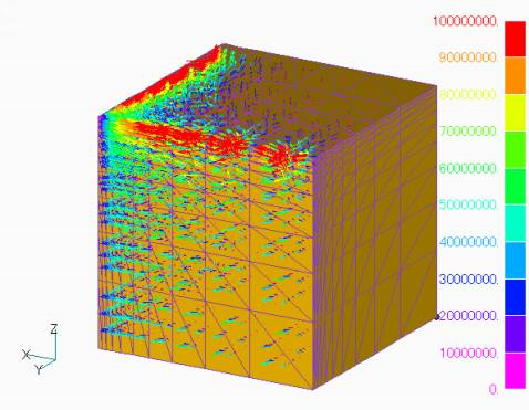
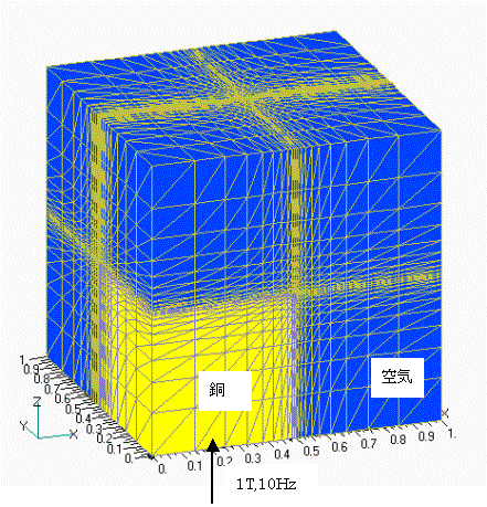
For example, consider the case of a rectangular body as shown in Fig. 1, where a uniform AC steady magnetic field is applied in the z-direction.
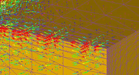
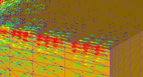
The rectangle is 1m on a side and 5×10⁷S/m. The magnetic field is assumed to be 1T at 10Hz. If we calculate with rectangular first-order elements, we can obtain a reasonable eddy current density distribution as shown in Fig. 1. However, when divided into tetrahedrons and calculated with first-order elements, the result is a wavy current density vector as shown in Figs. 2, 3, and 4.
To remedy this problem, EMSolution introduces and enables the use of node-second-order edge-first-order elements for all elements (hexahedral, tetrahedral, triangular prismatic, and pyramidal).
Explanation
This element has the same edge shape function space for magnetic vector potentials as the conventional first-order element, but it increases the degree of freedom of the edge shape function space for electric scalar potentials. For elements in the conductor region, a nodal shape function is added to a nodal point at the edge midpoint.
This element has the same edge shape function space for magnetic vector potentials as the conventional first-order element, but it increases the degree of freedom of the edge shape function space for electric scalar potentials. For elements in the conductor region, a nodal shape function is added to a nodal point at the edge midpoint.
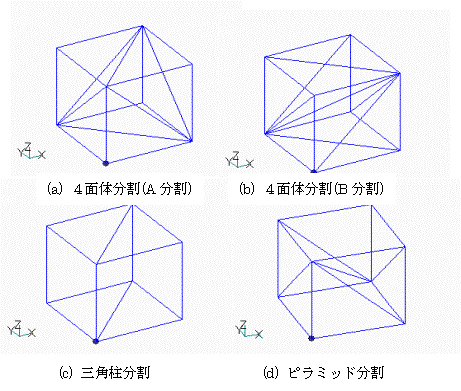
In the following, we show the convergence of the solution to the mesh in terms of eddy current heating calculations. As a test problem, we use the same one described above. In order to divide the surface into smaller pieces, the mesh division in each direction is divided so that the size is an geometric progression (equi-proportional sequence). The division into tetrahedra, etc. is based on rectangular division, and the rectangle is divided into several elements as shown in Fig. 8. For each rectangle, there are (a) 5 tetrahedral elements, (b) 6 tetrahedral elements, (c) 2 triangular prism elements, (d) 2 pyramid elements and 2 tetrahedral elements. The ratio of the minimum mesh width to the maximum mesh width is 20. The aspect ratio of the elements will also be this value 20.
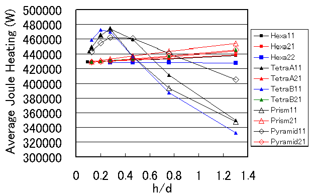
The relationship between mesh width and average Joule heating value for the various elements analyzed is shown in Fig. 9. The ratio of skin thickness (d) to minimum mesh width (h) is taken on the horizontal axis. The names of the lines indicate the element type, nodal order, and edge order; TetraA, TetraB, Prism, and Pyramid refer to divisions (a), (b), (c), and (d) of Fig. 8, respectively.
For example, Hexa11 represents a first-order (node-first-order edge-first-order) element. First, we see that all element types converge to the same value of 428 kW as the mesh is subdivided into finer and finer pieces. However, the convergence is very different. First, for the hexahedral element, the primary element and the node-second-order edge-first-order converge almost identically. For tetrahedral, triangular prism, and pyramid elements, the convergence of the first-order element and the node-second-order edge-first-order element is very different, with the first-order element converging very poorly and with large errors. Finally, convergence occurs only after h/d becomes smaller than about 0.3. In comparison, the node-second-order edge-first-order elements converge linearly to the solution, although the magnitude of the error varies depending on the element type.
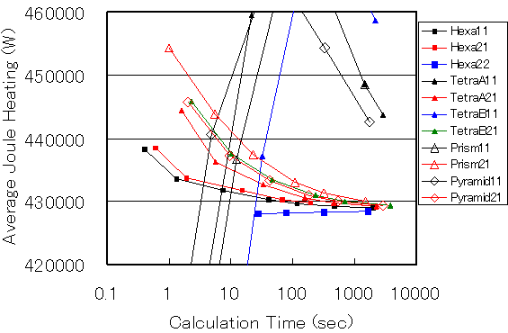
The stretched vertical axis of FIg.9 is shown in Fig.10. The error for the first-order hexahedral element is smaller than that for the tetrahedral and other elements. The error for the triangular prism element is higher. There is not much difference in the way the elements are divided into tetrahedrons. This figure shows that the accuracy of the hexahedral second-order element is very good, even when h/d is around 1, and the value remains almost the same as the mesh is made finer. However, the hexahedral second-order element requires a large amount of computation space and time.
Fig. 11 shows the computation time of EMSolution (Pentium 4, 2.53GHz) on the horizontal axis. 1,000 seconds of analysis will give an accuracy within 1% for any element type. However, it is necessary to use node-second-order edge-first-order elements for tetrahedrons, etc.
The results of this study can be summarized as follows
- Hexahedral elements have good accuracy, especially for secondary elements, even with rough meshes. In addition, the accuracy of node-second-order edge-first-order elements is almost as good as that of first-order elements, eliminating the need to use node-second-order edge-first-order elements. However, since we are analyzing a rectangular body in this study, a hexahedron seems to be a good fit, and care should be taken if there are other shapes or distorted hexahedrons.
- For eddy current analysis with skin effect, the use of node-second-order edge-first-order elements is desirable for elements other than hexahedra.
This node-second-order edge-first-order element has been available since EMSolution r9.7.3. Mixing of hexahedral, triangular, tetrahedral, and pyramidal node-second-order edge-first-order elements is also possible. However, it cannot be used when there are gap elements, etc. in the conductor because it has not been extended to plane elements. Also, it has not been extended to two-dimensional analysis. We are planning to extend the software to these applications in the future.
How to use
-
Set POTENNTIAL=2 in Handbook "2. Potential and Gauge Conditions" and use the
-
If you set NODE_ORDER=2 and EDGE_ORDER=1 in Handbook "4 Order of the Shape Function and Added Features", the calculation will be for a node-second-order edge-first-order element. The elements in the mesh file pre_geom will be converted internally to secondary elements even if they are first-order elements for the conductor region. Post data such as post_geom will be output as drcond-order elements. If the order of the geometry function is NODE_ORDER=2 and EDGE_ORDER=2, the analysis is performed as a node-second-order edge-second-order element.
-
The rectangular mesh for this study is generated by a function described in Handbbok "15. Automatic rectangular mesh generation". The input is as in the following example (for tetrahedron B division), where ELEMENT_TYPE: =0:hexahedron, =1:triangular prism, =2:tetrahedron, =3 (pyramid + tetrahedron), DIVISION_TYPE: =0:division A, =1:division B (applicable when ELEMENTTYPE=2), RATIO TYPE: =0:input split ratio (Ratio of consecutive dividion lengths), =1:input first to last mesh width ratio (for negative input for number of splits)
Download
Node-second-order edge-first-order tetrahedral element
In case of Division-B
・ input.txt
Analysis Examples by Functions
Convergence property improvement and speed-up methods
- Problems with flat tetrahedral elements and their countermeasures
- Node-second-order edge-first-order elements
- Joining hexahedral and tetrahedral elements
- Improved convergence of flat and elongated elements
- Fast convergence to steady-state solutions of time-periodic problems
- Steady-State Analysis of Induction Motors Using a Simplified Time-Periodic Method
- Steady-State Analysis of Rotating Machines by Simplified Multi-Phase AC EEC Method
- Parallel computing capability with OpenMP
- Restart analysis function for changing convergence conditions
©2020 Science Solutions International Laboratory, Inc.
All Rights reserved.


