Problems with electromagnetic force analysis
- TOP >
- Analysis Examples by Functions (List) >
- Problems with electromagnetic force analysis
Summary
EMSolution uses the nodal force method to determine the forces acting on magnetic materials and conductors. The nodal force method often gives accurate results, but sometimes gives questionable results. Here is an example.
Explanation
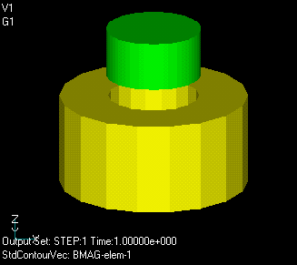
In the TEAM Workshop, Problem 23 is the problem of finding the electromagnetic force acting on a magnet. The model is shown in Fig. 1. The yellow-green cylinder is a magnet, which is magnetized downward. The yellow cylinder is the coil, and an upward force is generated in the magnet when an electric current flows through it. The analysis is performed as two-dimensional axisymmetric. The coil is defined by a LOOP in the deformation potential.
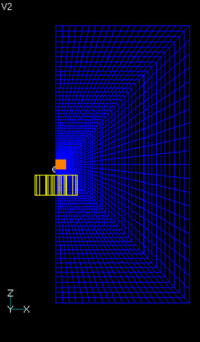
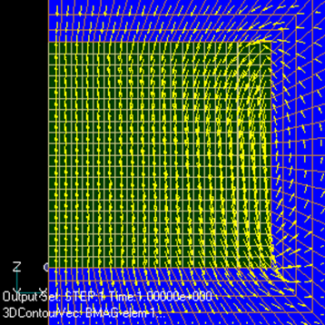
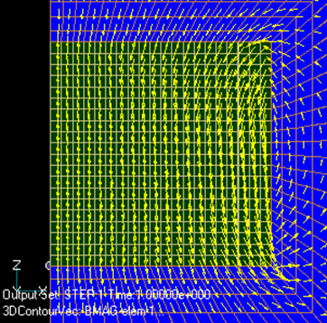
The obtained electromagnetic forces are shown in Fig. 2. Two results are shown, one with a mesh that is vertically symmetric at the center of the magnet (Fig. 3) and the other with an asymmetric mesh (Fig. 4). The asymmetric mesh produces a non-zero total force even when the coil current is zero, as can be seen by comparing Fig.3 and Fig.4, which are almost similar.
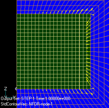
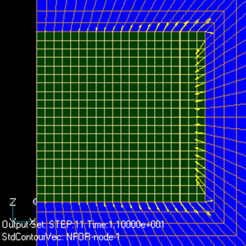
Fig. 5 and Fig. 6 show the magnetic flux density distribution in both meshes. Almost no difference is observed. Fig.7 and Fig.8 show the nodal force distribution. In this case, too, the difference is small. However, as for the total force, the asymmetric mesh with current 0 in Fig.2 shows a non-zero electromagnetic force as an error. Fig.7 shows a symmetrical mesh for a coil current of
If the total force is the only issue, the surface magnetization or surface current method can be used to determine the magnetization or current in the magnet, and then the electromagnetic force due to the external magnetic field can be determined. In this case, the self-force of the magnet itself does not appear, so there is no cancellation error and the result may be obtained with high accuracy. EMSolution does not currently employ this method. The following are possible countermeasures.
- The mesh should be as fine as possible.
- If symmetry is present, the mesh should also be as symmetrical as possible. In particular, if there is a state in which electromagnetic forces do not act, analyze that state and make the mesh as small as possible so that the total force is as small as possible.
- As can be seen in Fig. 2, the error due to mesh distortion does not seem to depend much on the externally applied magnetic field. For this reason, it is possible to subtract from the calculation results the error in the state where the total force should be zero.
To improve the problem of electromagnetic force analysis, a method to calculate electromagnetic forces including nodal forces in the air region is shown in "Improvement of Electromagnetic Force Analysis".
Download
・ input
・ pre_geom2D.neu : Mesh file (symmetric & asymmetric mesh)
Analysis Examples by Functions
Electromagnetic force
©2020 Science Solutions International Laboratory, Inc.
All Rights reserved.


