Electromagnetic field analysis software

Electromagnetic field analysis software
NETWORK and CIRCUIT settings in a three-phase circuit
- TOP >
- Analysis Examples by Functions (List) >
- NETWORK and CIRCUIT settings in a three-phase circuit
Summary
NETWORK and CIRCUIT are two methods for considering connections to electrical circuits in EMSolution. NETWORK is considered intuitive and easy to understand because it uses the circuit elements and power sources described in the circuit diagram and their connections as input data. CIRCUIT, on the other hand, organizes the circuit connections into only independent variables and gives the connections as matrices, which is like directly representing the circuit equations to be solved. Therefore, CIRCUIT is not suitable for very complex calculations, partly because of the difficulty in creating input data. However, since NETWORK is an optional module, you may want to use only CIRCUIT for simple circuits.
Therefore, we will explain the correspondence between NETWORK and CIRCUIT using a commonly used three-phase circuit as an example.
Explanation
NETWORK
NETWORK is a method of describing circuit elements and their connections from a schematic to an EMSolution input and is considered easy to understand because it is intuitive. Therefore, we will first show the circuit diagram of the model to be calculated and create data using NETWORK in order to make an easy-to-understand comparison with CIRCUIT. Fig. 1 shows the schematic of a three-phase circuit. The blue letters in the figure indicate element numbers, and the red letters indicate terminal numbers. This circuit is the one connected to the “Modeling of unipolar squirrel-cage induction motor” and you can download the mesh, input files, etc. The orange part in Fig. 1 represents the coil, which is divided into elements and subjected to magnetic field analysis using the finite element method. The part of the circuit that is in series with each phase is called a branch, and each branch is referred to as Branch 1, Branch 2, and Branch 3. Hereafter, the subscripts for elements, power supplies, etc. correspond to the respective branch numbers. The resistance (

Fig.1 Three-phase circuit diagram in NETWORK
Next, external resistors (R1, R2, R3), external self-inductances (L1, L2, L3), and external mutual inductances (M12, M23, M31), such as external elements and cables not included in the finite element mesh model, are represented as NETWORK resistance elements R, inductance elements L, and mutual inductance elements M. Also, the constant-voltage power supply is set as the voltage source element VPS and the constant-current power supply is set as the current source element CPS. A constant-voltage power supply VPS is used here, and V1, V2, and V3 give the three-phase voltage conditions for the U, V, and W phases with equal magnitudes and phase delays of 120° in that order. Therefore, equation (1) holds.
The NETWORK data are set in the input file as shown in Fig. 2. However, external self and mutual inductance are not considered, and all coil resistances of the mesh model are assumed to be

Fig.2 NETWORK input
Fig. 3 shows the time function given to a constant-voltage power supply, including its magnitude and phase over time. The voltage magnitude is V (≈81.649 V), which is the maximum value obtained by converting the line voltage of 100 V to phase voltage, the period is 0.2 s (frequency 50 Hz), and the phase is 0, -120, and -240 degrees at t=0 for phases U, V, and W, respectively.

Fig.3 NETWORK input (time portion)
Contrasting with the variables in Fig. 1, we see that equation (2) holds:
Although the constant supply voltage is given as three-phase input data, the obtained analysis results generally show that the currents are not necessarily three-phase. For example, the mesh geometry of the “Modeling of unipolar squirrel-cage induction motor”, which is also an example of this analysis, is not symmetrical with respect to the three phases, so the internal inductances are not equal and
Perform a linear ac steady-state analysis (AC). Since the model is an induction machine, material nonlinearity and the effects of slip frequency and slot harmonics would normally appear in the current waveform, but since this is an AC analysis, the results are obtained assuming the material is linear. The results for the output circuit element at t=0 are shown in Fig. 4.
The ID No. in Fig. 4 corresponds to the element number in blue in Fig. 1. 1 to 3 are the coils of the mesh, 4 to 6 are the external resistors, and 7 to 9 are the power supplies, representing the current and voltage phase difference flowing through each. 1 to 3 also show the amount of magnetic flux chained to the coils. This is the amount of magnetic flux chained in the coil per number of turns, as explained in “Handling of inductance in external current field source (COIL)”. It can be seen that the conditional equations (1) and (3) for the current and the voltage of the power supply are all satisfied. Although not shown here, results other than
CIRCUIT
CIRCUIT is a method of setting up independent closed loops without treating the schematic as it is in NETWORK. As is well known, the number of independent closed loops is the number of co-trees in graph theory. Since the number of independent closed loops in the circuit shown in Fig. 1 is 2, we define closed loops A and B as shown in Fig. 5, and let the currents flowing in each loop be the closed circuit currents
Similarly, the following determinant relationship holds for the voltages
The matrix representing the relationship between the branch and the closed loop expressed in equation (5) is called the closed path matrix or the tieset matrix. As can be seen from equations (4) and (5), the matrix representing the relationship between the branch and the closed-loop current and voltage is a transpose matrix.

Fig.5 Three-phase circuit diagram in CIRCUIT
Fig. 6 shows the CIRCUIT settings. External resistance and inductance are entered as matrices. The number of sources is set in NO SERIES, and the number of independent sources is set as POWER SUPPLIES. Also, set the connection matrix in equation (4) as CONNECTION MATRIX.
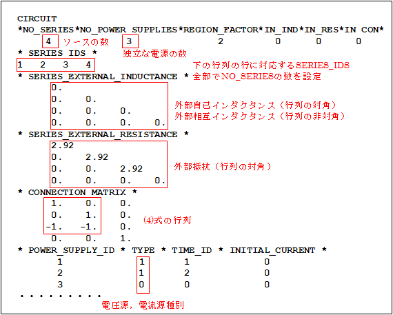
Fig.6 CIRCUIT input-1
Since the voltages

Fig.7 Magnitude and phase of power supply voltage

Fig.8 CIRCUIT setting in the input-2 file
As in the NETWORK case, an AC analysis was performed and the results for the output circuit at t=0 are shown in Fig. 9.
ID No. 1, 2 and 3 of Sources in Fig.9 represent Branch 1, Branch 2 and Branch 3, respectively. Amplitude (Current) is the branch currents
We hope you now understand the relationship between NETWORK and CIRCUIT in a three-phase circuit. Whether you set up a NETWORK or a CIRCUIT, please simulate the circuit you are assuming. As indicated in the text, the data used here can be found in “Analysis of Induction Motors” for CIRCUIT and “Handling of Rotor Bars and End Rings in Two-Dimensional Analysis of Squirrel-cage Induction Motor” and “Modeling of Unipolar Squirrel-cage Induction Motor” for the NETWORK setting method.
Analysis Examples by Functions
Coupled with external circuit system
- Example of Periodic Current Change Input of Constant-current Power Supply
- NETWORK and CIRCUIT settings in a three-phase circuit
- Transformer Analysis
- Improvement of Power Supply Input Method
- Time-dependent variable resistance elements
- Y-connection and
- NETWORK Nonlinear Element Table Entry
- REGION_FACTOR and series and parallel circuits in EMSolution
- Coupled analysis with MATLAB/Simulink
- 鎖交磁束ベースのモータビヘイビアモデル
©2020 Science Solutions International Laboratory, Inc.
All Rights reserved.