Improvements to near-axis problems in axisymmetric calculations
- TOP >
- Analysis Examples by Functions (List) >
- Improvements to near-axis problems in axisymmetric calculations
Summary
In the past, axisymmetric calculations of the EMSolution did not correctly obtain the magnetic field distribution in the vicinity of the central axis. We have attempted to improve this situation by transforming the coordinate system of the shape function. With this improvement, the distribution near the central axis is smoother and more accurate.
Explanation
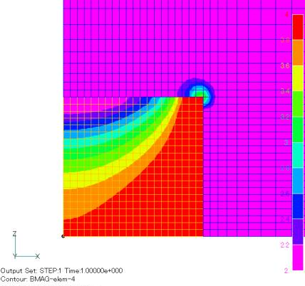
When axisymmetric calculations are performed by EMSolution, the magnetic field distribution near the central axis cannot be obtained correctly. For example, when a uniform magnetic field is applied to a cylindrical magnetic material as shown in Fig. 1, the magnetic field strength distribution is calculated as shown in Fig. 2. The magnetic field distribution near the center is unnatural. This is due to the fact that in the edge element finite element method, when an element is distorted, the interpolation function is distorted accordingly. When considering a magnetic flux penetrating a trapezoidal shaped surface, the interpolation function becomes stronger on the short side, making it difficult to represent a uniform magnetic field. In EMSolution, the plane is extended in the angular direction in a two-dimensional axisymmetric analysis. Therefore, near the central axis, the lengths of the central and opposite sides differ greatly, and the magnetic field calculation results were also incorrect because of this.
We have attempted to improve this situation by transforming the coordinate system of the shape function. The magnetic field strength distribution became natural as shown in Fig. 3, and we believe that the accuracy was improved. Away from the central axis, the result is almost the same as the previous one, and we believe that the previous one still shows a normal distribution if we do not care about the area near the central axis.
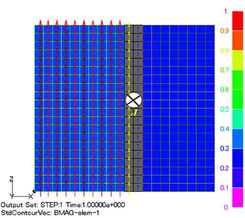
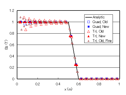
Next, for a very simple case, we calculate the magnetic field of an infinite length solenoid coil: the model looks like Fig. 4, where the gray area represents the coil and the current is applied so that the central magnetic field is 1T. Plotting the magnetic flux density in the z-direction, we see Fig. 6. In the conventional model (Quad,Old), the magnetic field near the center axis deviates from the theoretical value, but in the improved model (Quad,New), it agrees with the theoretical value with very good accuracy.
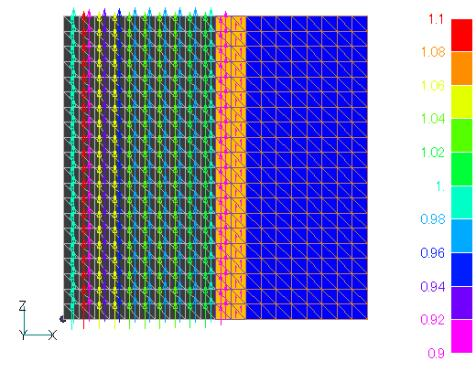
In the case of triangular elements, as shown in Fig. 5, the magnetic field near the central axis is unnatural as it is in the conventional case. Depending on the orientation of the array of elements, the magnitude of the magnetic flux density rises and falls, oscillating in the radial direction (Fig.6, Tri, Old). In this example, oscillations of about ±10% are observed. This oscillation appears similarly when the mesh is made finer; Fig. 6 shows the case where the mesh width is halved for Tri. Old, Fine. The error decreases quickly with distance from the center, but the width of the oscillation remains the same.
With this improvement, the distribution near the center axis is smoother and more accurate, as shown as Tri and New in Fig. 6. Although the mesh is regular, it agrees with the theoretical solution with an accuracy of more than 5 orders of magnitude. In the part of the coil where the current is flowing, the magnetic field should vary linearly, but a linear triangular element cannot represent this, resulting in a staircase-like distribution with or without this improvement.
How to use
No mesh or other data needs to be changed, just set the option METRIC_MOD in the input file as follows. This function should only be used for axisymmetric analysis where the current is in the angular direction and the magnetic field is in the r,z plane. Please do not use it in other cases and set METRIC_MOD=0 (or no input). We hope you will give it a try.
Download
Cylindrical magnetic body
・ input
・ pre_geom2D.neu
Solenoid Coil
・ input
・ pre_geom2D_QUAD.neu (quadrangle mesh)
・ pre_geom2D_Tri.neu (triangle mesh)
Analysis Examples by Functions
Two dimensional analysis
- Analysis by two-dimensional approximation
- Computation of two-dimensional axisymmetric problems using pyramid (quadrilateral pyramid) elements
- Improvements to near-axis problems in axisymmetric calculations
- Division of a quadrangle element tangent to an axis at a single point into triangular elements
- Magnetic field analysis of solenoid coil
©2020 Science Solutions International Laboratory, Inc.
All Rights reserved.


