Iron loss calculation using half-cycle periodicity
- TOP >
- Analysis Examples by Functions (List) >
- Iron loss calculation using half-cycle periodicity
Summary
As shown in "Fast Convergence to Steady-State Solutions of Time-Periodic Problems" and "Steady-State Analysis of Induction Motors Using a Simplified Time-Periodic Method", periodicity of each half-cycle generally holds for synchronous machines, and the periodicity holds for induction machines for each stator and rotor.
Explanation
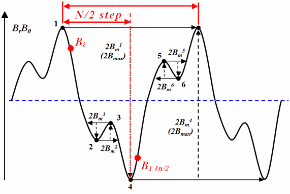
n the case of time-periodic problems, the eddy current loss has a waveform with a peak at each half-cycle. The eddy current loss in the stacking direction, when calculating iron loss, can be considered in the same way, and is equivalent to the case where the half cycle is multiplied by two to obtain one cycle. On the other hand, when hysteresis loss is calculated from the magnetic flux density waveform, the peak-to-peak value is used to calculate the maximum hysteresis loss loop as shown in the figure below, which requires data for one cycle. Therefore, as a method to calculate hysteresis loss in a half cycle, if the first half cycle is inverted after the half cycle in Fig. 1 to form the second half cycle, the data for the second half cycle can be created using the first half cycle.
If the cycle is divided into
In the case of iron loss, where one cycle is divided into
In the case of a strictly synchronous machine, the rotor side is superimposed with DC in one periodicity, so the half periodicity does not hold, and the difference may be large depending on the drive conditions. Therefore, this method is not strictly applicable to synchronous machines. However, considering the accuracy of the iron loss itself, it may not be a difference to be concerned about, but it is necessary to pay attention to it. In the second example below, we apply this method to the iron loss calculation of an IPM motor and evaluate it.
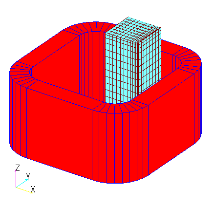
As an example, we first examine a simple model shown in the iron loss calculation by post-processing (Fig. 2). Calculation method 1 represents the method obtained from the maximum value of the magnetic flux density, and calculation method 2 represents the method obtained from the magnetic flux density waveform. Since the input is a sinusoidal waveform, the half-periodicity is valid, and the in-plane direction eddy current loss by FEM as well as the lamination direction eddy current loss are consistent. For the same reason, hysteresis loss is also consistent.
Table1 IEEJ Model Iron Loss
| One cycle | Half cycle (first half cycle used) | |||
| Calculation Method ① | Calculation Method ② | Calculation Method ① | Calculation Method ② | |
| Eddy current loss in-plane direction [ | 0.957 | 0.957 | 0.957 | 0.957 |
| Eddy current loss in stacking direction [ | 0.403 | 0.483 | 0.403 | 0.483 |
| Hysteresis loss [ | 1.656 | 1.656 | 1.658 | 1.656 |
| Total loss [ | 3.016 | 3.097 | 3.019 | 3.097 |
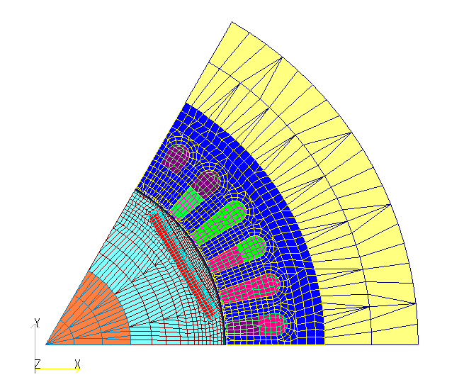
Next, we apply it to the IPM motor model, which was also used in the” Fast Convergence to Steady-State Solution of Time-Periodic Problems” (Fig. 3). Although half-periodicity does not strictly hold on the rotor side, we will try to verify its practicality. For simplicity, a two-dimensional model is used here for the current source analysis, and the iron loss is calculated under the maximum torque operation condition. The electromagnetic steel plate is assumed to be 50A1300 as in the above model. Table 2 shows the iron loss calculated for one cycle, and the iron loss calculated using the first and second half of the cycle using the half periodicity. The results for both half-cycles are in good agreement with those for the first cycle, although there are some differences. We hope that this level of difference can be permissible for synchronous machines.
Table 2 IPM Motor Iron Loss
| One cycle | half cycle | |||
| first half of the cycle | late cycle | |||
| rotor | Eddy current loss in stacking direction [ | 379.97 | 379.97 | 379.99 |
| Hysteresis loss [ | 103.57 | 111.35 | 111.36 | |
| stator | Eddy current loss in stacking direction [ | 2787.48 | 2787.48 | 2785.92 |
| Hysteresis loss [ | 5324.34 | 5324.28 | 5328.60 | |
| Total loss [ | 8595.36 | 9603.08 | 8605.87 | |
Since induction machines have slip, it is better to calculate the iron loss at the power frequency for the stator and at the slip frequency for the rotor. In this case, when the slip is small, as in rated operation, the slip frequency is smaller than the power frequency, and a large number of steps are required to calculate one cycle of the rotor. However, if half periodicity is used, it can be calculated in half the cycle.
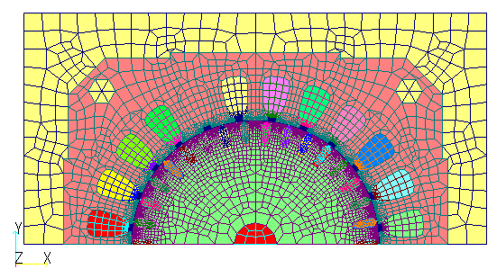
As an example, we apply it to the model used in the handling of rotor bars and end rings in the two-dimensional analysis of a cage induction machine (Fig. 4). The gap section is divided 180 degrees into 408 meshes, and the analysis is performed with one step per mesh, so that if the power frequency is 50 Hz and the slip is 0.25, one cycle at the power frequency is 306 steps and that at the slip frequency is 1224 steps. If we use the half periodicity, we only need 154 steps and 613 steps, respectively, which halves the computation time.
The calculated iron loss is shown in Table 3. Since only one peak to peak is considered when calculating hysteresis loss, the rotor hysteresis loss in the power cycle and stator hysteresis loss in the slip cycle are not calculated correctly but are shown in parentheses for reference. As mentioned earlier, the eddy current loss is almost the same value because it is time averaged regardless of the cycle, but the hysteresis loss shows a difference. Comparing the results for the rotor and stator separately, the results calculated using the half-periodic method are in good agreement with those calculated using the single-periodic method.
Table3 Induction motor iron loss
| stator | Rotor cycle | ||||
| One cycle | first half of the cycle | One cycle | first half of the cycle |
||
| rotor bar | Eddy current loss [ | 37.04 | 37.08 | 37.01 | 37.01 |
| rotor | Eddy current loss in stacking direction [ | 0.95 | 0.95 | 0.95 | 0.95 |
| Hysteresis loss [ | ( 0.55 ) | ( 0.50 ) | 0.95 | 0.95 | |
| stator | Eddy current loss in stacking direction [ | 3.18 | 3.17 | 3.19 | 3.19 |
| Hysteresis loss [ | 6.91 | 6.88 | ( 5.31 ) | ( 7.44 ) | |
| Total iron loss [ | ( 11.58 ) | ( 11.49 ) | ( 10.39 ) | ( 12.52 ) | |
The above demonstrates that iron loss can be calculated in half the number of steps of one cycle by using the half-periodicity. When the slip is small in the induction machine in the above example or when a PM motor is driven by a PWM inverter waveform, the number of calculation steps required to calculate one cycle is significant, so the half-periodicity is considered valuable.
How to use
The basic parameters for iron loss calculation are the same as for post-processing iron loss calculation. When the AVERAGE option is set to -1, iron loss is calculated at half cycle.
Set STEP_INTERVAL to
Download
IPM Motor
・ input2D_40_5_static.ems:Static magnetic field analysis for initial values
・ input2D_40_5.ems:Transient analysis
・ inputPost2D_40_5.ems:For one cycle iron loss calculation
・ inputPostHalf2D_40_5.ems:For half cycle iron loss calculation
・ pre_geom2D.neu
・ rotor_mesh2D.neu
Induction Motor
・ inputNETWORK_Y_AC.ems:AC steady-state analysis for initial values
・ inputNETWORK_Y_1125rpm.ems:Transient analysis
・ inputPostNETWORK_Y_1125rpm.ems:For one cycle iron loss calculation
・ inputHalfPostNETWORK_Y_1125rpm.ems:For half cycle iron loss calculation
・ pre_geom2D.neu
・ rotor_mesh2D.neu
Analysis Examples by Functions
Iron loss, permanent magnets and laminated iron cores
- Iron loss calculation using half-cycle periodicity
- Analysis of laminated iron cores by homogenization method and output of magnetic flux density of iron section of laminated iron core
- Analysis using nonlinear two-dimensional anisotropic magnetic properties
- Magnetization input to MAGNET by function
- Iron loss calculation by post-processing
- Evaluation of the rate of decrease from the input magnetization to the operating point and permeance coefficient of permanent magnets
- Demagnetization analysis of permanent magnets
- Analysis considering temperature dependence of magnetization properties
©2020 Science Solutions International Laboratory, Inc.
All Rights reserved.


