Analysis using gap elements
- TOP >
- Analysis Examples by Functions (List) >
- Analysis using gap elements
Summary
Gap elements are used to simulate thin insulation layers in conductors and air gaps in magnetic materials. There is a limitation when using gap elements in the insulating layer of a conductor and simultaneously using a surface inflow current source (SUFCUR). This is because both the gap element and SUFCUR for a conductor utilize an electrical scalar potential. Using the gap element and SUFCUR, a voltage can be applied to a closed bulk conductor loop. We will illustrate the use of the gap element through an example. The gap element can be used commonly in static, steady-state, and transient magnetic field analysis.
Explanation
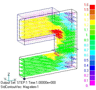
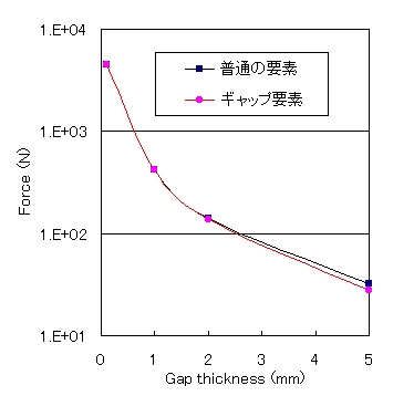
If there is a thin air gap in a magnetic circuit, analysis using ordinary finite elements requires very thin elements, resulting in poor convergence of the ICCG method. In this case, approximating the gap with a gap element facilitates the analysis. Consider the model shown in Fig. 1. The model uses the 1/4 symmetry condition. The coil uses surface-defined current 1 (SDEFCOIL). The gap surface is defined by a surface element. The gap surface must be defined as a single element overhanging the air region. For each element representing the gap surface, a unique property number is assigned and a file input (input.1mm) is defined. For the surface element properties, enter TYPE=2, conductivity 0, specific permeability 1, and the gap thickness in meters. Volume elements are defined as having no gap. Both sides of the volume element should be defined as separate property. The mesh is entered by pre_geom2D.neu and 2D_to_3D. The arrow distribution in Fig. 1 is the source current distribution given by SDEFCOIL. The resulting flux density distribution is shown in Fig. 2, and the nodal electromagnetic force distribution is shown in Fig. 3. List1 shows the electromagnetic forces output in the file output. In this case, the electromagnetic force in the z direction is meaningful. The total value includes the nodal force in the air part, which appears as an error. In this case, the sum of the upper yoke and coil electromagnetic forces and the lower yoke electromagnetic forces should match in action-reaction, but the difference should be considered as an error. Fig. 4 shows a comparison of the attraction force between the gaps when using ordinary elements and when using gap elements. When using ordinary elements, one-layer-thick hexahedral elements are placed in the gap. The agreement is better when the gap spacing is small. For example, for a 0.1 mm gap, the number of iterations of the ICCG method using ordinary elements is 274, whereas using gap elements, the number is reduced to 93, which requires less computation time.
List.1 Contents of the output file Output
How to use
Defines a gap element.
Download
Analysis Model
・ input_1mm.ems
・ pre_geom2D.neu
・ 2D_to_3D
©2020 Science Solutions International Laboratory, Inc.
All Rights reserved.


