Insulation gap in conductor
- TOP >
- Analysis Examples by Functions (List) >
- Insulation gap in conductor
Summary
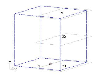
Gap elements can also be used when the conductor has an insulation gap: assume that there is a conductor of rectangular cross section in the z-direction and a voltage is applied, as shown in Fig. 1.
Explanation
A surface inflow current source (SUFCUR) is used here. The upper and lower surfaces impose the Bn=0 surface symmetry condition, and the other far boundaries are also assumed to be Bn=0. The conductor is assumed to have an insulating layer to block the current. Define the planes as shown in Fig. 2. Faces 21, 22, and 23 are insulating surfaces. Face 1 is assumed to be the current inflow face for SUFCUR. Face 21 is oriented downward and face 23 is oriented upward. Face 22 and face 1 can be either. Faces 21 and 23 are on symmetrical boundary planes and the positive orientation of the faces must be in the direction of the conductor. The gap face must be defined at least one layer beyond the conductor as shown in the figure. This model results in current flowing in from the bottom half of the conductor and out from the top half. The analysis is an AC analysis, with a voltage of 1 V at 50 Hz applied between the top and bottom surfaces. These are defined in the input and pre_geom.neu file.
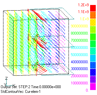
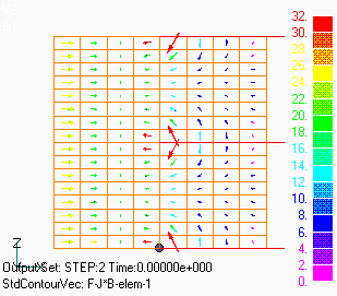
Fig. 3 shows the obtained current distribution. The current flows from bottom to top due to the applied voltage but is intercepted by the gap and bypasses the gap. Fig.4 shows the average heat generation distribution output to the heat file. The heat generation is concentrated at the gap tip. Fig.5 shows the electromagnetic force distribution obtained from the Lorentz force (force_J_B file). The force to open the gap works. To improve the accuracy, it is necessary to make the mesh at the gap tip finer.
Download
・ input
・ pre_geom.neu
©2020 Science Solutions International Laboratory, Inc.
All Rights reserved.


