Reference position in mesh deformation motion analysis
- TOP >
- Analysis Examples by Functions (List) >
- Reference position in mesh deformation motion analysis
Summary
EMSoluition assumes that the object in motion (the moving part) is a rigid body and can only handle motion in one direction (x, y, z, rotation). Therefore, a single position coordinate is sufficient to represent the position. The reference position described in Handbook "19.3 Motion of Deformed Mesh deform_mesh (2D)" represents the position of the movable part, which is freely defined by the user for his/her own convenience. Please think of the reference position as a reference position for setting other input parameters, not as an input to EMSolution. For example, you can define the reference position as when the center of the movable part is at the origin of the mesh model, or for a plunger , it can be defined as when the movable part is at the lowest point where it touches the fixed part.
Explanation
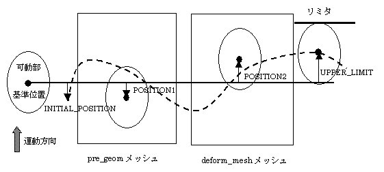
The position of a moving part due to time variation (motion) is expressed as a relative position (signed distance, or angle in the case of rotation) from the above reference position. POSITION1 represents the relative position of the movable part in the pre_geom mesh from the reference position. In Fig. 1, POSITION1 is the position of the movable part in the pre_geom mesh that is slightly below the reference position.
If you want to define the position of the moving part in the pre_geom mesh as the reference position, then POSITION1 = 0. POSITION2, which represents the position of the movable part in the deform_mesh, is entered in the same way. As can be seen in Fig. 1, POSITION2 in deform_mesh should correspond to the position of the moving part in POSITION1 in the pre_geom mesh. If the control elements described in "Improvement of deformation motion function" are used, deform_mesh is automatically generated at the POSITION2 position.
When giving a time variation of the position of the movable part, it is also expressed as a position relative to the reference position. When performing kinematic coupling, the position-related quantities (INITIAL_POSITION, LOWER_LIMIT, UPPER_LIMIT in "18.6 Coupled Analysis with Equation of Motion ", and EQUIL_POSITION in "18.6.1 Spring Data”, POSITION in "18.6.1 Spring Data” and "18.6.2 Damper Data", etc.) are all expressed as this relative position. INITIAL_POSITION is represented as the initial relative position at the start of the motion, and LIMIT is also represented as the limiter position as a relative position. Velocity-related parameters are not related to the reference position. The position of the moving part is output as an analysis result in the motion file, but this position is also relative to the reference position.
As explained above, in deformational motion analysis, all position-related quantities change depending on how the reference position is taken. However, since it is a parallel motion (translation) in one direction, it only changes by a constant amount. Positive and negative reversal of direction cannot be handled.
As an example, here is the analysis data of the plunger shown in "Improvement of deformation motion function". In the original data, the reference position is defined as when the gap is zero. As a test, we define the initial position (gap of 0.01 m) as the reference position. The calculated position change is shown by the red line in Fig. 2, which is just a 0.01m shift from the original analysis.
How to use
The plunger input data shown in "Improvement of deformation motion function" is changed as shown in Table 1. The red boxes indicate the changed areas, and you can see that all values have been subtracted by 0.01.
Table 1. Input data with the reference position changed to the initial position
For data when the reference position is set to zero gap, please refer to "Improvement of deformation motion function".
Analysis Examples by Functions
Coupled equations of motion and external circuit systems
- Three-dimensional analysis of plunger-type electromagnets and hinged electromagnetic relays with deformation
- Reference position in mesh deformation motion analysis
- Improvement of deformation motion function
- Plunger motion analysis
- New functionality added to Dynamic module – Relative position dependence of mass and restart function –
©2020 Science Solutions International Laboratory, Inc.
All Rights reserved.


