Inductance Calculation for COIL
(external current magnetic field source)
- TOP >
- Analysis Examples by Functions (List) >
- Inductance Calculation for COIL (external current magnetic field source)
Summary
In EMSolution, the self- and mutual inductance of an air-core COIL (external current field source) must previously be entered in the CIRCUIT or NETWORK. Now the inductance of the COIL can be calculated within EMSolution, instead of having to calculate it separately.
Explanation
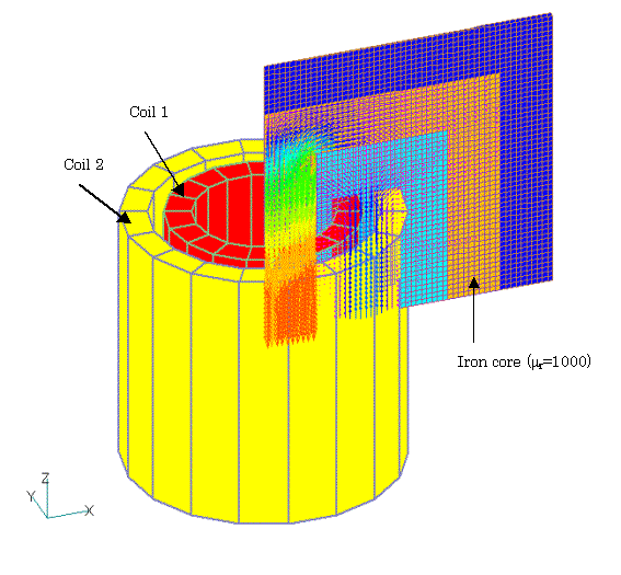
Inductance calculations are performed for the GCE, ARC and LOOP elements. The self and mutual inductances of the other elements are not calculated and are set to zero. The mutual inductance between GCE, ARC and LOOP and the other elements is also calculated. As an example, consider an axisymmetric two-dimensional, ac steady-state analysis as shown in Fig. 1. Assume that two series of LOOP coils are wound on an iron core, with voltage applied to Coil 1 and Coil 2 short-circuited.
The calculated inductance of the air core is output to the output file and is also used in the analysis. The coil is assumed to be 100T with a radial width of 1 cm and an axial width of 10 cm.
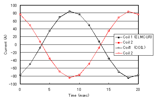
A comparison of the same analysis with an analysis using ELMCUR (internal current source) is shown in Fig. 2. When ELMCUR is used, the inductance of the air core is included in the analysis domain, and the results of the internal calculation of the inductance of the air core using ELMCUR and COIL are in good agreement, as shown in Fig. 2.
How to use
To use this function, set the CALC_IND option to 1.
The COIL settings for this example are as follows. Add integral elements (LOOP-, GCE-, ARC-) data in addition to the conventional input (LOOP data). These data are identical to the corresponding LOOP, GCE, and ARC data, except for the last row. Three-dimensional Gauss integral of the product of the magnetic vector potential and the current ($(A・J)$) is performed in the region defined by the integral elements. The area of integration is the COIL region limited to the mesh model area.Region factor is defined in CIRCUIT or NETWORK and is the reciprocal of the REGION_FACTOR for the entire COIL. In this example, the upper half of -0.5 to 0.5 degrees is defined. The angle is specified by DELTA_THETA (1 degree in this case), which adds upper half of 1 degree of ARC-data to LOOP. The integral elements do not contribute to the magnetic field. The purpose of this double data entry for the same coil is to reduce the computational complexity and also to be used for COIL electromagnetic force calculations.
For LOOP-, GCE-, and ARC-data, the number of divisions and the number of Gauss integration points are specified at the end. NDIV is the number of equal divisions of the element in the current direction. Gauss integrals are performed on the divided elements at INT_X × INT_Y points in the cross-section direction and INT_Z points in the current direction. Depending on the element geometry and magnetic field distribution, INT_X=INT_Y= 5, INT_Z=3 seems to be sufficient for accuracy. In the case of this axisymmetric two-dimensional calculation, NDIV=1 and INT_Z=1 are sufficient since the magnetic field does not change in the current direction.
For CIRCUIT and NETWORK data, there is no need to input the inductance for the air core, which was previously required. However, the coil resistance must be entered. In this example, the calculation results from the ELMCUR analysis are entered. Also, REGION_FACTOR is important, so please be careful not to make a mistake.
Attention
In this analysis example, when COIL is used, the inner coil and air region of the iron core is the reduced potential region (POTENTIAL=1), and the other regions are the total potential region (POTENTIAL=0). In this case, the far boundary is the total potential region and the boundary conditions apply to the total potential.
In this example, the normal component of the total flux density is assumed to be zero. Since the coil is surrounded by an iron core and the magnetic field leaking out of the core is considered small, it is more appropriate to impose the boundary condition on the total magnetic field.
Download
・ input.ELMCUR_CIRCUT
・ input.COIL_CIRCUIT
・ input.COIL_NETWORK
・ pre_geom2D.neu :Mesh data
*This data also includes data for the calculation of COIL electromagnetic forces. For more information about COIL electromagnetic forces, see" COIL inductance and electromagnetic force calculations". Analysis Examples by Functions
External current magnetic field source
- About the multi-potential method
- Definition of COIL (external current field source) by hexahedral element mesh
- Magnetic field distribution calculation in a COIL-only model
- Circuit calculation with COIL (external current field source) only
- COIL inductance and electromagnetic force calculations
- Inductance Calculation for COIL (external current magnetic field source)
- Handling of inductance in external current field source (COIL)
- About COIL Move
- Problems with external magnetic field current sources in the case of translational periodicity
- Notes on the use of GCE (rectangular current element)
©2020 Science Solutions International Laboratory, Inc.
All Rights reserved.


