Magnetic field distribution calculation in a COIL-only model
- TOP >
- Analysis Examples by Functions (List) >
- Magnetic field distribution calculation in a COIL-only model
Summary
COIL (external current magnetic field source) allows you to define coils independently of the finite element mesh and calculate the magnetic field produced by the coils.
Even in a COIL-only model, the magnetic field evaluation points of B_INTEG can be input as mesh data, and its magnetic field can be calculated and output using the Biot-Savart law. This function allows the calculation of the magnetic field due to COIL with high accuracy without setting boundary conditions.
Explanation
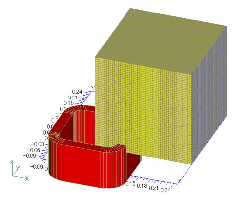
As an example, let us calculate the magnetic field generated by the COIL (red) shown in Fig. 1 in the region of the magnetic field evaluation point (yellow) in B_INTEG. The shape and dimensions of the COIL are described in the input data. To set the magnetic field evaluation points of B_INTEG, the mesh data, B_integ_mesh file, is used as input data.
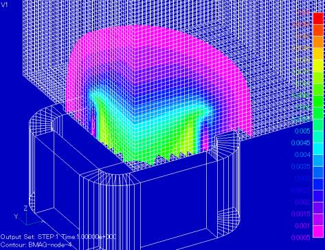
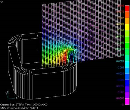
The file format is the same as the conventional pre_geom, etc. When the analysis is executed, the magnetic field is calculated at each node position defined in B_integ_mesh and the results are output to the B_integ file in the specified format. The B_integ_mesh file should contain not only nodal data but also element data, as it will be used for contour display in post-processing. Element data can be either solid or shell (plane) elements. The post_geom file does not include the B_integ_mesh data, but outputs only the COIL geometry. Fig.2 shows the magnetic field distribution calculated by the above function and displayed by FEMAP. fig.3 shows the magnetic flux density vector distribution with the shell element mesh as input data.
In the previous EMSolution, when the evaluation point was far enough from the COIL, it automatically approximated the COIL entered in the 3D geometry as a line current, but now a judgement value to approximate the line current can be entered for the distance from the evaluation point to the COIL. At sufficiently far distances, the magnetic field created by the COIL input in the 3D geometry and the one approximated by the line current agree very precisely, and furthermore, the calculation may be faster if the COIL magnetic field is calculated by the line current approximation. In addition, the accuracy has been improved as a result of the improved COIL calculation method. The coil geometry dimensions used in this example are the benchmark model used in " Static magnetic field analysis using COIL (external current magnetic field source)" etc. and reported in "Three-Dimensional Static Magnetic Field Numerical Computation Techniques", IEEJ Technical Report No. 286.
How to use
In "input 10. input/output files" of the HandBook,
- Enter the file format number of B_integ_mesh in INPUT_MESH_FILE.
- Set MESHLESS=1.
- Enter the file format number of B_integ in POST_DATA_FILE.
- If MESH (FILE output) = 1, COIL shape data is output to post_geom.
- Set B_INTEG=1.
- Enter the number of COIL series to be included in the calculation (NO_COIL_SERIES).
- Set MESH_INPUT=1.
- Enter as many COIL series numbers as the number of coil series (NO_COIL_SERIES).
Note: Symmetry data such as XSYMMETRY is not meaningful but should not be excluded.
COIL data input is the same as before. However, LINE_APPROX, which is a judgment value for the distance from the evaluation point to COIL for the aforementioned line current approximation, has been added. What this means is that if the shortest distance from the centerline of the rectangular cross section of the coil created by LOOP, GCE, and ARC to the evaluation point is more than LINE_APPROX times the length of half the long side of the rectangular cross section of the coil, the calculation is performed replacing LOOP, GCE, and ARC by line current (FGCE and FARC) .Note that at the boundary between volume currents (rectangular cross-sectional pass-through currents) and line current approximations, continuity with respect to space may be poor. If you want to include all of the volume integrals without line-current approximation, set a sufficiently large number (see the input example below). On the other hand, if you want to approximate all of the line current, set the value to 0. If LINE_APPROX is set to any COIL data, it will be applied to all COILs.
Download
・ input
・ B_integ_mesh.neu :Mesh file (magnetic field evaluation points)
Analysis Examples by Functions
External current magnetic field source
- About the multi-potential method
- Definition of COIL (external current field source) by hexahedral element mesh
- Magnetic field distribution calculation in a COIL-only model
- Circuit calculation with COIL (external current field source) only
- COIL inductance and electromagnetic force calculations
- Inductance Calculation for COIL (external current magnetic field source)
- Handling of inductance in external current field source (COIL)
- About COIL Move
- Problems with external magnetic field current sources in the case of translational periodicity
- Notes on the use of GCE (rectangular current element)
©2020 Science Solutions International Laboratory, Inc.
All Rights reserved.


