EMSolution Basics 4-2
Edge element method
- TOP >
- What is EMSolution >
- Basics of EMSolution (list) >
- Edge element method
The $A-\phi$ edge element finite element method is a relatively new analysis technique that became popular in the 1980s, but its advantages have been widely recognized and it is used in EMSolution. In the conventional nodal element method, each node is assigned the three vector components of $A$ as unknowns, whereas in the edge element method, each edge is assigned the line integral of $A$. The edge element shape function is characterized by continuity of only the tangent component at the element boundaries and does not assume continuity in the normal direction.
The introduction of the edge element solves what was previously difficult or unclear. It is well known that spurious solutions in high-frequency analysis have been eliminated [20] , but many things have also been solved in the low-frequency domain.
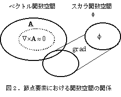
First, there is the solution of the gauge problem. In the nodal el-ement method, a Coulomb gauge was imposed by the penalty method or other methods to fix the gauge, but the necessity of this method and the weight of the penalty were unclear. In some cases, the problem could be solved by inserting appropriate boundary conditions. [21,22] The problem with the nodal method is that the non-rotation field (function space with zero rotation) in the finite element function space used is unclear (Figure 2), and it seems that a number of innovations were necessary to eliminate this field.
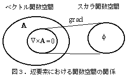
With the introduction of edge elements, the gauge problem was solved at once [13]. First, nodal elements are difficult to transform in a discretized function space, but in an edge element function space, it is now possible to transform as in a continuous field. Gauge indefiniteness is meaningful only when gauge transformations are possible, and in the $A-\phi$ method, vector fields $A$ and scalar fields $\phi$ can now be freely transformed. In the discretized edge element function space, the non-rotating fields in the vector field are represented by the gradient of the scalar field, and the gradient of the scalar field can be constructed to be contained in the vector field (Figure 3). This allows for a clear separation of the non-rotating fields. This means that, when the potential is expressed as $E=-\dot{A}-\nabla\phi$, $\dot{A}$ and $\nabla\phi$ originally represented the same single thing, allowing them to be interchangeable with each other.
As mentioned above, the fact that gauge transformations are pos-sible even in discretized function spaces means that indeterminacy will remain in the equations unless some gauge transformation is imposed.
One way to fix the gauge is by means of tree structure (Tree, Co-tree)). [13,23] This is done by decomposing the edges in a finite element mesh using a network analysis method. A tree is the set of the maximum number of edges in a finite element mesh that do not form a closed loop, and a co-tree is the set of edges that, when added together, form a closed loop. The decomposition is not unique, but the number of edges in each is fixed. After such a decomposition, the degrees of freedom of the Tree edges are usually set to zero and excluded from the variables. This method is theoretically beautiful because it clearly removes indeterminacy, but it is known to slow down the convergence of the cointegrating gradient method (to an extreme degree).[24]
Another way of fixing the gauge is to impose the Coulomb gauge on the edge elements as well, in the form of Lagrange multipliers method [25]. There, the weak form of the Coulomb gauge ($\nabla \cdot A$=0) is imposed as a condition. Although this method makes the meaning of the potential easier to understand by imposing a physically mean-ingful gauge, it is considered to be disadvantageous as a solution method because it adds undetermined multipliers, which increases the number of unknowns, and because it is difficult to solve (it seems) due to the lack of positivity of the matrix. Even without doing so, it is possible to find a solution that satisfies the Coulomb gauge by gauge transformation from a solution that does not satisfy the Coulomb gauge [26] .
For the conductive part, a gauge of $\phi = 0$ can be imposed [13] . This alone leaves the non-conducting part indeterminate, but it can be solved by the ICCG method, usually referred to as the $A$ method. Thus, there are various gauge-fixing methods, and the potentials obtained are different, but they can be shown to be mutually gauge-transformable, and when physically meaningful electric and magnetic fields are calculated, the results are exactly the same.
EMSolution allows the user to include $\phi$ = 0 gauges and gauge con-ditions by tree structures. However, it has been shown theoretically that the convergence of the ICCG method is slow for gauges with tree structures [28], and also practically it is very computationally time-consuming and not very practical. Gauges also have fewer unknowns, but convergence is also slower. In particular, it seems essential to use $\phi$ as a variable in low-frequency eddy current analysis.
One of the things made easier and more understandable by the edge element method is the boundary condition. Typical boundary conditions in electromagnetic field analysis are the electric wall con-dition ($B_n$ = 0) and the magnetic wall condition ($H_t$ = 0). For the $A$-$\phi$ edge element method, it is sufficient to have zero fixed degrees of freedom for the edge on the face of the electric wall, and for magnetic walls, it is sufficient to have free degrees of freedom. This is not the case for nodal elements, where three components must be considered for inclined boundary surfaces, and the story gets more complicated for corner points.
For edge element shape functions, the normal components of the vectors are not continuous at the element boundaries. For example, if the vector potential $A$ is represented by an edge element, the discontinuity above appears in the electric field $E$. Although it is sometimes disliked that the potentials are discontinuous, this is more reasonable. For example, suppose that the eddy currents are calculated using the $A$ method and there is a discontinuity in the conductivity. In this case, the normal component of the eddy currents should be continuous, and the normal component of $A$ should be discontinuous. The same story applies to the continuity of the flux normal component in the $H$ method (which imposes the gauge con-dition in the $T-\Omega$ method). Using a function with continuous normal components for nodal elements will not work on such a discontinuous surface. [22]
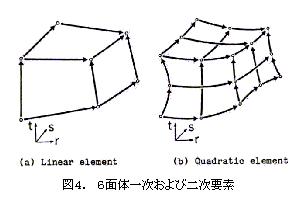
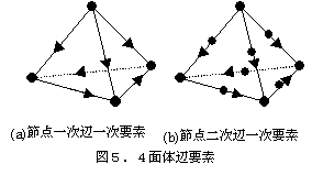
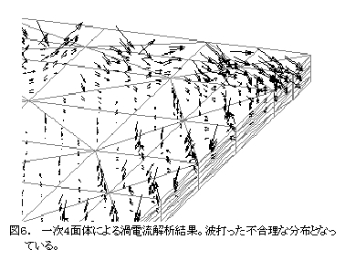
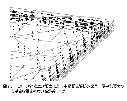
In EMSolution, the edge element types are tetrahedral (4-sided Nedelec primary), triangular prismatic (9-sided), hexahedral (12-sided) primary elements, and secondary hexahedral elements (36-sided) (Figure 4) corresponding to the serendipity family 20-node hexahedron [17]. Recently, it was found that the eddy current density distribution is not smooth when using primary tetrahedral elements in eddy current analysis with large skin effects, so we devised a primary edge element with a secondary nodal element function and showed that a reasonable solution can be obtained even with flat tetrahedral elements [2] (Figure (5, 6, 7).
©2020 Science Solutions International Laboratory, Inc.
All Rights reserved.


